

By Dave McCracken
This system combines two classification screens to more-effectively separate material-feed into three separate size-fractions, each which is directed into a different recovery system.

Classification is the Key to Fine Gold Recovery
It is well-established that if you want to effectively recover finer particles of gold, you must first separate them from the larger-sized materials which are being washed through your recovery system by a higher-velocity flow of water. The small-sized material can then be directed to a milder-flow of water over a shorter set of riffles. The smaller you can classify the size of the material, which can be directed by and even milder flow of water over lower-profile riffles, the finer-sized gold that you can effectively recover.
This is all rather easy to accomplish with surface processing plants where earth-moving equipment can be used to feed a plant some distance above the ground. Feeding a plant well above the ground allows plenty of drop for water and gravity to direct material through multiple sizes of classification screens. Then, gravity can be used to direct the different size-factions of material to separate recovery systems with controlled water-flows and riffle sizes specifically designed to recover gold effectively from each size-fraction.
Conventional Suction Dredges do not allow for Much Classification
I am not sure what the exact formula is, but I know from long experience that every inch you lift the feed of a suction dredge above the surface of the water, you lose a considerable amount of suction-power at the dredge nozzle. Therefore, since we have to accomplish both classification and gold recovery from a feed that can only be effectively lifted about 4-to-6 inches above the surface, our options are pretty limited.
Dredge manufacturers have worked out different ways to direct classified materials into slower-moving recovery systems. Generally these methods fall into three categories:
2) Placing a classification screen towards the head of the sluice box, and then directing the classified material to one or two completely separate sluices which have a slower-moving flow of water over lower-profile riffles. This was most commonly seen in the form of side-by-side triple sluices during the 80’s and early 90’s. While effective, the problem with the side-by-side sluices is that the side sluice(s) normally have to be placed on top of the dredge’s pontoons. Therefore, in order for gravity to make everything work right, the initial feed to the dredge has to be lifted higher out of the water. This causes a power-loss at the nozzle. So you do not see as many side-by-side recovery systems in production on suction dredges these days.
3) Placing a classification screen somewhere towards the upper-end of the recovery system, and directing the classified material to a slower-moving recovery system which is located directly below the main box. This is commonly referred to as an “over-under” recovery system, and remains in popular use today. An over-under system is most commonly accomplished in the same basic sluice box, which is constructed with a removable false bottom. By this, I mean two separate recovery systems, one sitting over top of the other, in the same sluice box.
I cannot go into which of these systems are better or worse; because there are too many variables in play, and experienced prospectors can work it out to get the best recovery possible out of any of these designs, each which would likely be comparable to the other. That’s because all three of these system concepts depend upon a single classification screen to remove some portion of the smaller-sized material from the higher-velocity water-flow which is required in a dredge.
This particular discussion has more to do with the effectiveness and size of material-classification. Remember, with conventional suction dredges, we are using water-flow to move all our material across any classification screen(s) that we are using. The larger the dredge, the faster and more powerful the water-flow must be to wash larger-sized rocks and a larger volume of material through the sluice. The faster the flow, the less time that smaller-sized material has to drop through a classification screen. The smaller the openings in the screen, the less opportunity smaller-sized material has to drop through the screen. The shorter the screen, the less opportunity smaller-sized material has to drop through the screen.
Each of these factors combine into to the effectiveness of the dredge’s classification. For example, the substantial flow of water to move 5-inch sized material over 10 inches of 1/8th inch punch plate does not present much opportunity for minus-1/8th material to drop through the screen. So while a separate slower-moving recovery system might be doing a better job recovering smaller-sized gold, perhaps the classification system is only allowing 5% of the finer-sized gold to be directed into the slower-moving recovery system. In other words, the effectiveness of your recovery system is largely affected by how you are attempting to classify and separate the smaller-sized material.
Therefore, on the subject of fine gold recovery with suction dredges, our first challenge is to try and accomplish effective classification as best we can out of a strong flow of water (strong enough to move the largest rocks you are sucking up through the recovery system).
Years ago, we overcame this whole challenge on commercial dredges by working out a mechanized shaker screen at water level which provided 100% classification of the dredge feed. Minus-sized material from the screen was dropped into a sump where it was redirected by a gravel pump to an elevated feed on a surface-type recovery system either on the shore, or on a separate floating platform.
But it is impractical and too expensive to try and place a mechanized classification screen on smaller-sized dredges — which also must remain more portable for sampling. Therefore, on conventional dredges, until someone comes up with something different (if ever), we must continue to make due with a water-flow to wash material across our classification screen(s). With this in mind, here are a few principles which I believe to be true:
2) The smaller the holes in the screen, the less finer-sized material you can expect to drop through the openings out of the high-velocity flow required to move larger material through your sluice box. Example: Using the same flow of water and material, you could expect more fine-size material to drop through a 3/8-mesh screen, than a 1/8-mesh screen. This is because the larger openings provide a bigger doorway for material to drop through.
3) The shorter the length of a classification screen, the less fine-sized material you can expect to drop though. Therefore, we want the classification screens to be as long as we can get away with. Longer screen means more opportunity for finder-sized material to drop through.
4) Effective classification of finer-sized material can be accomplished better in stages. For example, first drop 3/8-minus material out of the fastest flow in the box. Then, using a slower flow of water, direct the minus-3/8 material over a 1/8-inch screen.
5) Since we only have 4 or 5 inches of drop to work with from the feed of a conventional suction dredge, there is only room for two levels of classification screen before we must drop the finest-sized material into a recovery system. Otherwise, we will be underwater where reduced gravity is not going to allow water-flow to work for us, anymore.
What to use for a fine-gold recovery system?
 As I have explained elsewhere, I believe it is necessary to direct finer-sized material over lower-profile riffles that will continue to remain fluid under a mild flow of water, even when they are full of concentrated (heavy) material. If you have not reviewed the theory on this, I strongly suggest you read “The Size of Riffles.”
There are different kinds of low-profile fine gold recovery systems on the market. Just take a look around and make your own choice.
We have been using the green, plastic Le Trap sluices to reduce the volume of our dredge and high-banking concentrates all the way back to the early 90’s. I cannot overstate how effective these Le Trap Sluices are. When set up with the proper water-flow, a Le Trap will recover all the visible gold from a feed of minus-1/8th material with losses that are so minimal as to be meaningless. We know this from panning the tailings hundreds of times over the many years.
So when we needed something to recover overwhelming amounts of fine gold using a dredge on a river in Cambodia, I started giving a lot of thought to how we could more-effectively classify dredged material down to minus-1/8th, and direct the material in a controlled flow over Le Trap-type riffles.
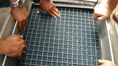
Several very experienced dredge-builders and I created the prototype several years ago from a Precision 6-inch dredge. To accomplish our objective, we assembled two layers of classification screen, each which could be independently raised or lowered, so that we could adjust the water-flow over the riffles, and over each of the screens. The top screen is 3/8-inch mesh. This is to allow the larger-sized material and strong water-flow to wash through the box without affecting the plastic riffles along the bottom. Minus-3/8ths material drops through the top screen onto a 1/8th-inch mesh screen, where the water flow is substantially reduced. Slower water-flow then allows finer-sized material more-extended contact with the 1/8th-inch screen.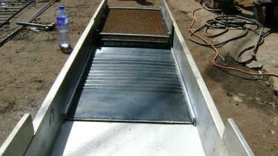
Material that drops through the 1/8-inch screen is then carried over the Le-Trap sluice by a mild flow of water. By adjusting the height of the lower screen over the plastic riffles, and the slope of the sluice box, we are able to control the amount of water-flow over the lower-profile riffles.
Since the sluice box in the 6-inch Precision was much wider than a normal Le Trap sluice, the prototype required quite a lot of work in a cut and paste project (using of 4 or 5 Le Traps) to create the first underlay recovery system for a dredge.
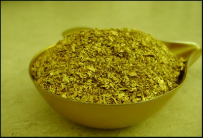
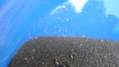 We invested quite a lot of time and energy into the prototype. All you have to do is look at how much (very fine) gold we found on that river in Cambodia to understand why we did it. We were shipping this 6-incher over to resume (sampling) where we had left off on that earlier project.
During trials on the Klamath, I was amazed at how much (very) fine gold we recovered out of just a minute or so of dredging loose material off the surface!
Our trial run on the Klamath River near Happy Camp in March several years ago turned up so much fine gold out of the lose surface gravel, that I hesitated over sending the 6-inch prototype to Cambodia!
I have been told for 30 years that there is so much fine gold in the river that we are losing out of our conventional dredges, if we could just recover it, we could make the river pay just by pumping any gravel! This new system seemed to prove that theory may be true, especially with these higher gold prices. But it was March and the Klamath was cold; so we shipped the original prototype dredge to Cambodia.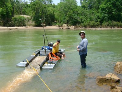
I devoted plenty of time in Cambodia (underwater) observing three separate flows of material coming off the back-end of the recovery system; and it was poetry in motion!
I have a non-disclosure agreement with our clients in Cambodia, so I cannot go into details or images of how well the new system performed over there. But I can say that I devoted a lot of time underwater watching water and material exit the sluice box in three separate flows; and the double-screen system is by far the best thing I have seen on a conventional dredge for effectively classifying material into three separate size-fractions.
Because of that, my experienced buddies and I invested quite a lot of time during the 2009 mining season to adapt the double-screen system to my 8-inch dredge. 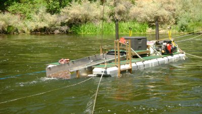
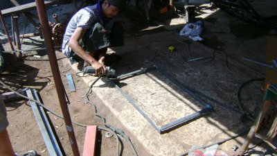
Building double classification screens, so they can be adjusted up and down to allow you to set three separate water-flows through the sluice box, requires quite a lot of labor! But getting this right is the foundation of this whole concept.
Here are some video links which demonstrate the system being used on my 8-incher. These give you a much better look at how we created a double-screen classification system over top of the fine gold recovery: Take a look at the size of the gold we were recovering!
As (bad) luck would have it, the State of California imposed a temporary ban on suction dredging just as we completed the double-screen refit on my 8-inch dredge. This forced us up onto the Rogue River in Southern Oregon, where we are limited to smaller-sized dredges. So my 8-incher had to be set aside.
Picking up on the idea of my double-sluice conversion over a plastic sluice, one industry-fabricator was recently promoting the idea of refitting conventional sluices (using the plastic sluice underlay) which do not include the double-screen classification, and do not allow the screens to be adjusted. I would advise caution on short-cutting these concepts. That is what prompted me to write this article. Since these conversions must be accomplished through custom shop work, I wanted to provide you with some background so you can make your own decisions.
While there is still a lot to learn, for the reasons I outlined above in points 1 through 5, I personally do not believe that you can classify raw material effectively from a 4, 5 or 6-inch (or larger) dredge being washed across an 8-mesh screen by high-velocity water.
I believe effective classification must be accomplished in stages; first to drop the 3/8-minus material out of the higher-velocity flow which is needed to push the larger-sized material through the sluice. Then, drop the 1/8-minus out of the much slower flow necessary to wash 3/8-inch material across the lower screen.
I believe you have to be able to adjust the height of each screen (set the water velocity) in order to get a workable water-flow over the riffles and over the 1/8-mesh screen. The water-flow cannot be so much that you boil-out the riffles, and it cannot be so little that you load the riffles. You also must not pack up the space between the two screens!
Eric Bosch and I first experimented with this double-screen concept in the early 90’s. But we made the mistake of fixing both screens (welded them where we estimated they ought to be). Our estimate of how much water-flow was needed between the screens was incorrect; the space between the screens packed solid with material; and the whole system failed.
Also, if you cannot adjust the water-flow over the riffles, and between the screens, you cannot compensate for different conditions in different areas.
 As an example, there is an overwhelming amount of heavy black sand and small iron rocks (and lead) along the Rogue River in Southern Oregon. We do not encounter this magnitude of heavies on our properties along the Klamath River in northern California. The heavies along the Rogue completely overwhelmed my fixed recovery system (buried the riffles on my 5-inch conventional dredge) at the beginning of last season. This prompted me to place smaller riffles below my (fixed) screen, spaced further apart. That worked better, and I recovered a lot of gold. But I believe I lost most of the (very) fine gold (I could see it in the last riffle) that was fed into my sluice box. This has prompted me to refit the recovery system on one of my 5-inch dredges for the upcoming season.
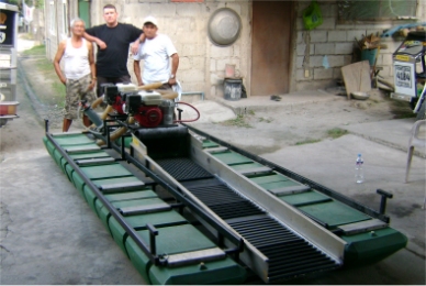
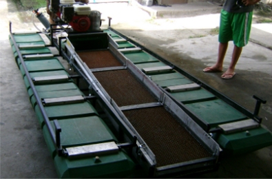
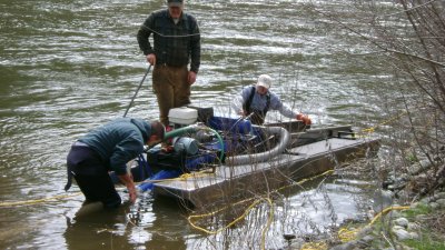
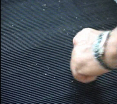
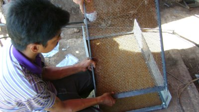
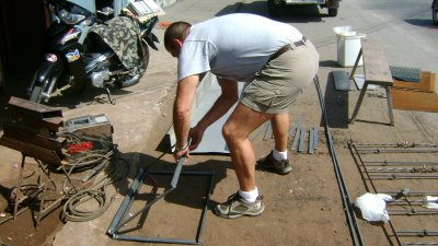
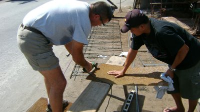
The images at the beginning of this article show an early version of the double-screen system that was designed for deposits we located in Cambodia. We did not find a single particle of gold on that river that was larger than the size of a pinhead. Since larger-sized gold was not present, we did not want to waste the (very) limited amount of room we had to work with by installing riffles for larger gold. Those images are helpful in showing the plastic sluice underlays (there are two of them, one following the other).
The images at the beginning of this article show the Cambodian version of the double-screen refit. Those images are helpful in showing the initial plastic sluice underlays that we were using (there are two of them, one following the other).
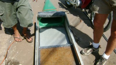
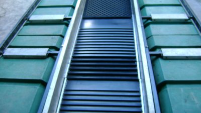
The images in this article also show a header section near the upper-end of the box. My initial theory was that the initial impact of the water and material must bottom-out on something other than plastic sluice underlays. We experimented with a combination of different kinds of heavy screens over top of miners moss or ribbed rubber matting to absorb the initial force of the water and material where it bottoms-out at the head of the sluice box. Fortunately, nearly everything we have tried in the header section seemed to work really well. As you will read below, we have since evolved completely away from using plastic sluice underlays… 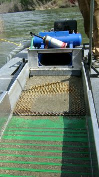
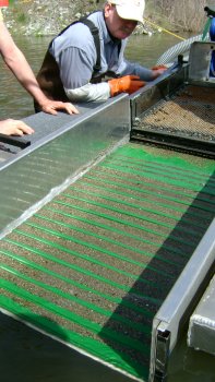
This is what the header area looked like under the screens when we shut the dredge off while dredging at production speed. You can see how classified material kind of mounds up there before flowing onto the slick plate of the riffle system. We are finding that quite a lot of (very) fine gold also gets trapped in the header section!
We have noticed that while in production, material tends to mound on top of the header section under the 8-mesh screen, and then wash off the mound onto the first sluice underlay. This is really good, as long as the mound does not rise up and pack-up the whole space between the screens.
While we were still using them, the plastic sluice underlays followed just behind the header section. This allowed water-flow and material to settle out and slow down before being washed across the lower profile riffles.
Notice that the shorter section of riffles (remains protected by the top screen) are present only to process classified material which washes across the 8-mesh (lower) screen in the box.
Adding larger riffles for bigger gold
We have since evolved the system, adding two sets of different-sized riffles to catch larger-sized gold. We accomplished this by replacing one of the 1/8-mesh (lower) screens with a solid bottom that supports both sets of the added riffles. The false bottom continues to allow an under current to wash minus 1/8th material across a low-profile underlay, just like in the Cambodia version.
The first set of riffles on top of the false bottom is designed to process the material that drops through the 3/8-inch screen, but is too large to drop through the 1/8th-inch screen (1/8th-to-3/8th size-fraction). This would be for small nugget-sized gold. That size-range of gold is very easy to recover.
As I discussed in The Size of Riffles, the height of a riffle necessary to recover a piece of gold normally does not need to be much taller than the size of the gold you are trying to trap. So the first set of riffles for larger gold can be rather short. Notice that the first set of riffles continues to be protected by an extension of the top screen.
Then we added a final set of open riffles (not covered by a classification screen) to catch any gold we might suck up that is larger than 3/8th-inch (larger nuggets). For example, depending upon where you dredge, the Rogue River in Southern Oregon can produce a lot of gold in these larger sizes. But the river is loaded with fine gold, as well.
It is kind of hard to see in the images; but if you look close, you can see the plastic sluice under the false bottom where we placed the riffles for larger gold.
Since you cannot buy these double-screen systems ready-made, you either have to refit your own sluice, or arrange with a capable fabricator to do it for you. With this in mind, I will follow with some basic directions which we have learned from building several of these systems:
Building the System
If you look at a Le Trap, you will see that it has 3 important sections: There is a slick plate at the top. This is vital; because it allows the water-flow to smooth out before material encounters the riffles. Then there are some short riffles. These capture all the gold unless you over-feed the box with too much material at once, or unless you completely fill the short riffles with gold. Then there are some deeper riffles which more-aggressively capture all the rest of the gold when you do over-feed the short riffles up front. “Overfeeding” has more to do with the amount of heavy iron material, than light sand or gravel. I will talk more about this down below.
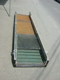
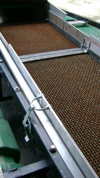
 This image shows two sluice underlays following the header section (with no screens on top)
When we planned these sluice underlay riffle-panels, we included the slick plate up front, and then went about 50/50 the rest of the way using short and deep riffles. We did this because I wanted more of the short-type riffles that work so well in the Le Trap. But I did not want to eliminate the deeper riffles which create such a strong back-flow, especially at times when lots of material is being fed across the box. But through extensive trial and error using the third evolution of this system this past season, we discovered that the higher velocity flows that are necessary to move volume-amounts of classified material across the plastic riffles were also causing some of the trapped fine gold to boil out of the system. Too bad! We then tried Keene’s new ribbed rubber matting (good stuff!) and ended up with the same result (we were losing some gold). So it appears that these plastic and rubber riffle systems are better suited for final concentrating work, rather than being used in the volume production setting inside of a dredge recovery system (more on this below).
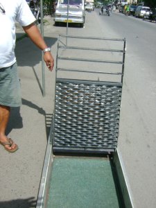
Because the double-screen assemblies are heavy, in order to manage them, you have to divide your sluice box into several smaller sections. How many sections depends upon how long your sluice box is. You will notice in the images at the top of this article that we divided my 5-inch dredge into three separate sections. One section is over the header area. The other two sections are over top of two identical sluice underlays. It is wise to divide the sluice underlay sections into exactly the same sizes. This way, the parts can be interchanged when it is time to reassemble your recovery system.
We build the double-screen assemblies so they rest exactly upon the sluice underlays. This allows us to take apart one only portion of the sluice box if that is all we want to look at or clean-up.
The screen assemblies are built so the aluminum side supports slide down inside the sluice box and sit directly on top of the side rails of the sluice underlays. This pins everything down snuggly against the bottom of the sluice box. Then we snap the screen assemblies down tight to make sure everything stays in place when we are running the dredge or moving it around on land or in the river.
Sluice Underlays
Through a very substantial amount of trial and error this past season, we discovered that both the plastic sluice material and also the new Keene rubber matting were losing gold from under the twin screens.
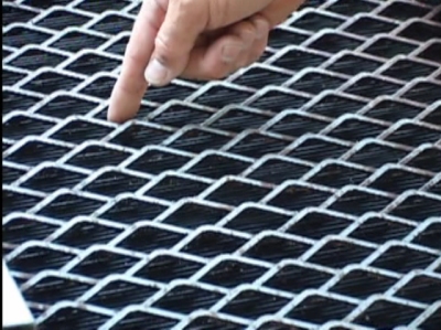
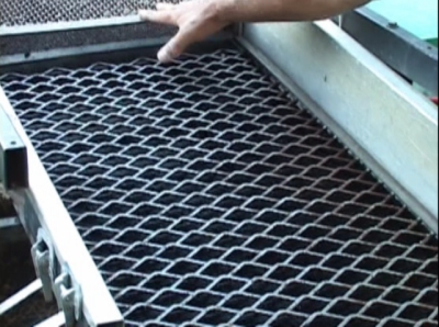 We finally found the right combination by using a wide, raised expanded metal over top of deep ribbed rubber matting. The aggressive expanded metal was dropping the gold out of the classified feed. Once it was in the ribbed mat, the gold was not getting away. This combination was so effective, we even replaced our header section with the same expanded metal, though we used miners moss underneath, rather than ribbed rubber matting.
We did multiple checks; and we were never able to find a single speck of gold in the final 25% of our recovery system, even though we were mostly dredging in fine gold pay-streaks (loaded with fines in the front section of the recovery system) all season.
This is important: The width of the sluice underlays (and screen assemblies) have to be a bit narrower than the inside of your sluice box. Otherwise, it is too difficult to get them in and out when you want to perform a clean-up or reassemble the recovery system. I always allow a margin of around 1/8th or 3/16ths of an inch, maybe even ¼-inch on a wider sluice.
Note: We have since replaced the sluice underlay in the drawing above by welding some 3/4-inch angle iron on both sides of the expanded metal to create side rails that the double-screen assemblies can rest on top of.
The following video sequence should give you a better idea of what we have ended up with as a sluice underlay:
The width of your side rails needs to be greater than the margin you are allowing between the sluice underlay and the side of your sluice box. This is so you will be sure that the sides of the screen assembly are going to slide down and meet the rails of the sluice underlay.
Double-screen Assemblies
 These add up to some weight; so you have to plan how to divide your sluice box into small-enough sections that you can lift the screen assemblies out of your sluice box without too much trouble. On the other hand, you want to minimize how many sections you have to make, because these are very labor-intensive to build.
The length and width of the screen assembly should match the sluice underlay, so that they will marry-up exactly when you set the screen assembly down on top of the underlay.
 You have to use aluminum plate for the sides to keep the overall weight of the screen assembly from adding up too much. The height of the sides needs to be at least as tall as your sluice box. I build mine high enough that I have room to adapt a latch to snap everything down tight.
Once you have the aluminum sides of your screen assembly cut to size, bring them all to your local machinist, and ask him to mill slots so that you will be able to raise and lower your two screens. If you bring the machinist one of the lag bolts you are going to use, he can mill the slots just wide enough to allow the lags to slide up and down freely, but not so wide that the lag is allowed to turn in the slot when you are tightening or loosening the nuts that hold the screens in place. Just to make sure I will have the full range of adjustment, I have the slots milled nearly the full height of the sides, to within about ¾ inch of the edge, equally at the top and the bottom. Each aluminum side needs three slots; one on each end and another in the exact middle.
You can source thin-headed lag bolts from fastener supply outlets. If you look, I’ll bet you can find them on line. If you cannot find them, then you have to grind the heads down on regular lag bolts, because normal heads are too thick and will take up too much space between the screens and the sluice box.
Helpful hint: The head-thickness of lag bolts on both sides of the screen assembly need to be included when you are deciding how wide your screen assembly and sluice underlay need to be for everything to slide in and out of your sluice box without too much difficulty.
Another helpful hint: If you cut the side plates all the same size, and have the machinist mill the slots exactly the same on all the plates, all the pieces will be interchangeable, and then you can jig-up to drill standardized holes in the side rails to your classification screens.
The lag bolts need to be heavy enough to support the weight of your screens (perhaps 5/16ths or 3/8ths). Different boxes have different widths, meaning heavier screens. It is better to go a little heavy on the lag bolts. The bolts need to be long enough to extend through the aluminum side, through the side rail of the screen, and have enough room for a flat washer and self-locking nut.
Ideally, you build all your screens exactly the same size, so they can be interchanged. We accomplish this by rigging up a jig to cut all the side rails exactly the same; then to weld the frames all the same; and then to drill all the bolt holes the same. We drill the bolt holes in the side rails a little large to allow some margin for error.
Side rails for the screens need to be heavy enough to support the weight of your screens with you standing on top of them. By heavy, I am discussing rail thickness. Because, if you go too wide, you will limit how close you can adjust the distance between the screens. Thicker 1.25-inch-wide strap has worked well on my refits for the screen side rails.
Unless you want to buy whole new sheets of screen (expensive), I suggest you source used screen at your local metal scrap yard. The one we go to in White City, Oregon nearly always has a large supply in all mesh sizes. I gather that commercial screening plants replace their screens pretty often – most of it still in good enough condition to meet our needs.
The top screen (around 3/8th-inch openings) needs to be heavy enough to span the length and width of your screen assemblies without needing additional support, and without bending or sagging when you stand on top of the finished screen.
The lower screen (around 1/8th-inch openings) needs to be heavy enough to span the length and width of your screen assemblies without needing additional support.
Helpful note: I experimented with a finer-mesh lower screen (about 1/10th-inch openings), and had trouble with small particles of rock plugging up all the holes. We call this “blinding.” It’s when the holes in a screen all become plugged-up (or overwhelmed by too much feed), preventing the screen from doing its job. So it would appear that you do not want to use a mesh on the lower screen much smaller than 1/8th-inch.
 We have had good luck cutting the screens to size using a cutoff wheel on a hand-held grinder. If your side rails are made of thick material, you should be able to cut the screen to size and weld it down directly on top of the side rail frame. Grind all the edges nice and smooth, so your hands are not getting cut up once you start working with these screens on your dredge.
Helpful note: If you weld the bottom screen on top of the side rails, and the top screen on the bottom of the side rails, you will be able to loosen or tighten the center bolts in the side plate much more easily. I am talking about the lag bolts which attach the screens to the aluminum side plates. If you end up with your center bolts between the screens, it is much more difficult to get at them!
Another helpful note: You might want to drill your holes just off center through the side rails. This way, you can still get a socket on the nuts after the screen is welded on.
These helpful notes are things I have learned the hard way!
When you assemble the screens, a good starting point would be so that the bottom screen rests maybe just a little more than an inch above the plastic sluice.
Helpful hint: If you make the side rails on your sluice underlay too tall, it will limit how far down you can slide your lower screen.
We have had pretty good results lifting the upper screen about 1.25 inches above the lower screen.
This is important: To add more flexibility, if not already present, we modify the sluice box supports on the dredge so that we can raise and lower the slope of the box. This creates a very helpful mechanism for adjusting flow rates.
Once in the field, you can make adjustments to sluice slope and height of each screen to work out the needed velocity in three separate water-flows: First, the water-flow across the sluice; then the water-flow between the screens; and finally, the water flow across the top screen.
I already discussed above how to replace the lower screen with a false flat bottom which you can place riffles on top of to recover the larger classifications of gold. In my view, it is more effective to do this in the lower section of the sluice box (though, I mounted the riffles for larger gold in the upper-end of the sluice on my 8-inch dredge). I know this viewpoint is not popular with some prospectors, because they do not want to chance losing a bigger piece of gold that is allowed to get so close to the end of the recovery system. My answer to this is that gold is really heavy stuff! If there is some anomaly (like the gold is attached to quartz rock which makes the piece lighter) that would keep it from trapping in a set of riffles in the back-end of the box, it probably will not drop out in the front portion of the box, either.
Other than in a very rare occasion, the vast majority of the gold you will recover is small enough to drop through an 8-mesh screen. Some important part of that gold is so fine as to be difficult to recover using the recovery system on a conventional suction dredge. The journey of fine gold through 20 feet of suction hose, and then up through a diffuser (flare jet) places most of this fine gold right on the bottom of the material as it first flows into the sluice – right where you want it; right where it is most likely to drop through the classification screens out of the higher-velocity flows, which otherwise can wash it through your box like sand. Better, I think, to get the minus-1/8th gold into a safe holding area as the first priority.
If you look closely at the diagram just above, you will see another reason to put the larger riffles towards the rear-end of a double-screen system. See how all or most of the fines are directed through an undercurrent below the larger riffles? This means the larger riffles will not be getting flooded and loaded up with fine-sized material. So, while fine material gets more exposure to low-profile riffles (where it belongs), the deeper riffles remain more open so that larger gold has a place to drop out of the flow.
But that is just my view. You guys can do it any way you decide to!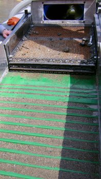
The reason you see rocks on top of the double-screens, is because we turned the dredge off while we were pumping at production speed. See how the riffles are working? They are not loading up, and they are not boiling- out. This means the system was working!
I do my classification and sluice flow adjustments when running the dredge at normal operating speed while I am feeding the nozzle at production speed in hard-packed streambed. I arrange for a second person to kill the motor without notice. Then, when I disassemble the system, I can see how the sluice and screens are performing while I am pumping gold and gravel into them at production speed.
Between these explanations, the drawings above, the images and the video segments, you guys (or the fabricator who will help you) should be able to see how these systems come together, and how they work. They provide you with a whole lot more than I started with!
Here follows a video segment we put together at the end of this last season which demonstrates the most recent evolution of this very effective dredge recovery system:
Other Considerations
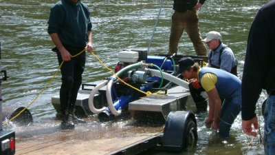
 Possible need for added floatation: As I mentioned above, these double-screen assemblies are heavy. So if you do a refit of your sluice, you may also consider adding some floatation to your dredge. When I refit the original 6-inch Precision dredge for Cambodia (image above), I also had new, larger aluminum pontoons made up to provide enough floatation so that I could also stand on the dredge while it was running. Nice!
Having enough water-flow to make double-screens work: Every dredge is a bit different. Before refitting your dredge with a double-screen system, you might turn the dredge up and watch the water-flow across your existing recovery system and estimate if you will have enough water volume to provide sufficient velocity to meet the needs of three separate flows.
Overfeeding the system: Every recovery system has its volume-limits! Since I find nearly all of my high-grade gold associated with hard-pack, I design my recovery systems to process average material which makes up normal hard-packed streambed that was put in place during the evolution of a major storm event. Normal streambed consists of rocks which are fitted together, with smaller rocks and pebbles in-between, with gravel, sand and silt filling the smaller spaces. When taking apart normal hard-packed streambeds, the smaller-sized material only comprises a small fraction of the overall volume. Therefore, I have yet to overwhelm one of these double-screen systems while production-dredging in hard-packed material.
On the other hand, if you go out on the river and just start pumping sand or loose, classified gravel (like tailings), a much-higher percentage of the material will penetrate the screens and you will almost certainly overload (blind) the sluice with too much material – and perhaps even pack-up the space between the sluice and the bottom screen. Let me be clear: This double-screen system is not designed to process sand or loose gravel deposits or tailings from some earlier mining activity!
This same concern is true for any type of recovery system used on a suction dredge. So it is important for you to be mindful of the material that you are feeding into your suction nozzle. If it is a layer of sand or loose gravel, you should either slow down; or you can speed up and pump it through as fast as you can; and then go up and make sure your system is no longer packed-up before you start feeding pay-dirt into your dredge.
The fine gold needs to be present: The only good place to test the effectiveness of your recovery system is when you are feeding high-grade into your dredge. The more gold you feed into the recovery system, the better you can see how well it is working.
Effectiveness cannot be discounted just because you see a speck or two of gold down towards the end of your box. The thing to look at is where most of the gold is stopping.
So many times, I have watched others decide their recovery system is not working, only because they are not recovering much gold. You cannot recover much gold if it is not present in the streambed that you are dredging! So I suggest you reserve judgment until you test your system in high-grade.
- Here is where you can buy a sample of natural gold.
- Here is where you can buy Gold Prospecting Equipment & Supplies.
- More About Gold Prospecting
- Gold Mining Adventures
- Schedule of Events
- Best-selling Books & DVD’s on this Subject